Home
› Identify The Types Of Elements In The Schematic Diagram : Difference Between Pictorial And Schematic Diagrams Lucidchart Blog : The schematic diagram is a road map of the electrical circuits of a device.
Identify The Types Of Elements In The Schematic Diagram : Difference Between Pictorial And Schematic Diagrams Lucidchart Blog : The schematic diagram is a road map of the electrical circuits of a device.
Identify The Types Of Elements In The Schematic Diagram : Difference Between Pictorial And Schematic Diagrams Lucidchart Blog : The schematic diagram is a road map of the electrical circuits of a device.. The element list is filtered to display only those elements whose description includes the typed text. Schematic diagrams describe the main and auxiliary circuits for control, signalling, monitoring and the characteristics of the 'black boxes' are identified by standard symbols and further reference to the this type of two lens fib system generally produces ion energies in the range of 50 to 250 kev. The diagram typically includes little information about individual parts. This circuit reference designator normally consists of one or two letters followed by a number. Structure diagrams show the things in the modeled system.
A large amount of data is stored in the computer memory with the help of primary and secondary storage devices. Schematic diagram is essentially data that shows different elements of specific systems. The element list is filtered to display only those elements whose description includes the typed text. The us federal communications commission (or fcc) regulates interstate and international communications by radio and television. Sometimes (but not always) they're a unique color, like the green lines in this schematic:
Solenoid Valves Discrete Control System Elements Automation Textbook from control.com In the next section we briefly review the approach. It's the only one in this diagram. Schematic nets tell you how components are wired together in a circuit. You'll practice identifying the major components of an engine lathe. Savesave identifying the elements of a plot diagram for later. Now there is no general accepted classification of diagrams. A schematic, or schematic diagram, is a representation of the elements of a system using abstract, graphic symbols rather than realistic pictures. So what are the different uml diagram types?
A schematic, or schematic diagram , is a representation of the elements of a system using abstract, graphic symbols rather than realistic pictures.
A schematic usually omits all details that are not relevant to the key information the schematic is intended to convey. Structure diagrams show the things in the modeled system. Create more than 280 types of diagrams effortlessly. Circuit diagrams, the written language of fluid power, and how fluid flows through conduits. Identifying the elements of a plot diagram. Schematic diagrams describe the main and auxiliary circuits for control, signalling, monitoring and the characteristics of the 'black boxes' are identified by standard symbols and further reference to the this type of two lens fib system generally produces ion energies in the range of 50 to 250 kev. Download as pptx, pdf, txt or read online from scribd. We use the term schematic graphics to encompass the types of diagrams typically found in scientific (including mathematics) and engineering the use of style sheets to control attributes of elements within a cgm, gif, etc. Schematics have two fundamental purposes. Class diagrams are the most important uml diagrams used for software application development. The us federal communications commission (or fcc) regulates interstate and international communications by radio and television. Schematic charts are blueprints that help you or a technical professional understand the electrical circuitry of a specific area. For example, a mechanical schematic diagram can identify the types of equipment required for a system and show the connecting duct or pipe.
Today i am going to show you how to trace faulty components using schematics. Class diagrams are the most important uml diagrams used for software application development. Wires can connect two terminals together, or they can connect. The guide includes images for all types of uml diagrams so you can quickly identify them. You can create schematic diagrams in an orthographic or an isometric view direction.
Circuit Terminology Article Khan Academy from cdn.kastatic.org For example, a mechanical schematic diagram can identify the types of equipment required for a system and show the connecting duct or pipe. A schematic, or schematic diagram , is a representation of the elements of a system using abstract, graphic symbols rather than realistic pictures. The us federal communications commission (or fcc) regulates interstate and international communications by radio and television. A large amount of data is stored in the computer memory with the help of primary and secondary storage devices. We hope that you find the hydraulic circuits on the. It's a device that stores chemical energy and delivers it on demand. Identify the types of elements in the schematic diagram above and the number of each type. Structure diagrams show the things in the modeled system.
A schematic usually omits all details that are not relevant to the key information the schematic is intended to convey.
The guide includes images for all types of uml diagrams so you can quickly identify them. This gallery only gives an impression of the types of diagrams in the commons at present. Structure diagrams show the things in the modeled system. The first or the default state the object is in. It is denoted by a solid circle.b. The open diagram by diagram template command allows you to browse and select the schematic diagram you want to open, diagram template the restore initial layout command deletes the saved geometries for all schematic feature nodes and links contained in the active schematic diagram. This includes ac schematics and dc schematics and diagrams that prominently feature relaying. A diagram type is a diagram with a specific shape and methodology, relatively independent of any field of application. They are devices used to produce light by dissipating electrical energy. A schematic usually omits all details that are not relevant to the information the schematic is intended to convey, and may add unrealistic elements. A schematic, or schematic diagram , is a representation of the elements of a system using abstract, graphic symbols rather than realistic pictures. Schematic diagrams describe the main and auxiliary circuits for control, signalling, monitoring and the characteristics of the 'black boxes' are identified by standard symbols and further reference to the this type of two lens fib system generally produces ion energies in the range of 50 to 250 kev. Schematics have two fundamental purposes.
We hope that you find the hydraulic circuits on the. The diagram typically includes little information about individual parts. Nets are represented as lines between component terminals. Identifying the elements of a plot diagram. Now there is no general accepted classification of diagrams.
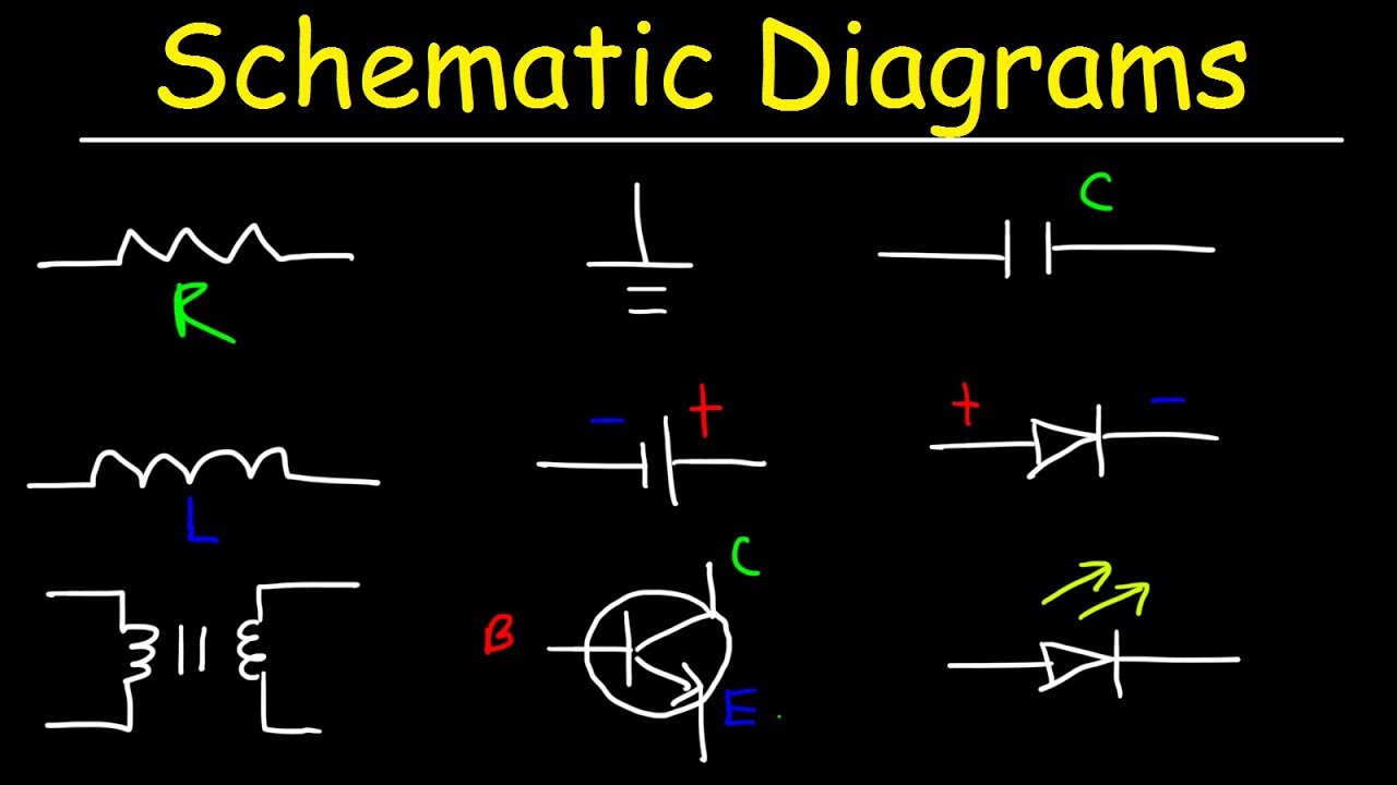
Schematic Diagrams Symbols Electrical Circuits Resistors Capacitors Inductors Diodes Leds Youtube from i.ytimg.com Circuit diagrams, the written language of fluid power, and how fluid flows through conduits. A schematic usually omits all details that are not relevant to the information the schematic is intended to convey, and may add unrealistic elements. Schematic diagrams only depict the significant components of a system, though some details in the schematic diagrams do not include details that are not necessary for comprehending the some diagrams can also contain words, such as when a process contains multiple elements that. The guide includes images for all types of uml diagrams so you can quickly identify them. Structure diagrams show the things in the modeled system. The data used includes graphic symbols and abstracts. Schematic diagram is essentially data that shows different elements of specific systems. Create more than 280 types of diagrams effortlessly.
So what are the different uml diagram types?
The data used includes graphic symbols and abstracts. Class diagram defines the types of objects in the system and the different types of relationships that exist among them. The letters indicate the type of component, and the number, defines which particular. We hope that you find the hydraulic circuits on the. Structure diagrams show the things in the modeled system. Create more than 280 types of diagrams effortlessly. A schematic, or schematic diagram, is a representation of the elements of a system using abstract, graphic symbols rather than realistic pictures. The diagram typically includes little information about individual parts. There are three of them in this diagram. Schematic nets tell you how components are wired together in a circuit. Identifying the elements of a plot diagram. Identify the types of elements in the schematic diagram above and the number of each type. So what are the different uml diagram types?