Home
› Control Diagram Symbols / Stock Vector Icon Pack Of 25 Line Signs And Symbols For Sport Flow Control Diagram Chart Editable Vector Design Elements Stock Vector Image Art Alamy : Ciircuits, diagrams & symbols includes:
Control Diagram Symbols / Stock Vector Icon Pack Of 25 Line Signs And Symbols For Sport Flow Control Diagram Chart Editable Vector Design Elements Stock Vector Image Art Alamy : Ciircuits, diagrams & symbols includes:
Control Diagram Symbols / Stock Vector Icon Pack Of 25 Line Signs And Symbols For Sport Flow Control Diagram Chart Editable Vector Design Elements Stock Vector Image Art Alamy : Ciircuits, diagrams & symbols includes:. There are three major transistor types: Below is a table of the most commonly used electrical symbols used in circuit diagrams. Arduino led matrix tutorial, best and efficient method of controlling 74595, how to connect 74595 to 8*8 led matrix, best and simple circuit to. Electrical & electronic symbols and images are used by engineers in circuit diagrams and schematics to show how a circuits components are connected together. Similarly, the verbiage in the text calls for surge and lightning protection.
In complex diagrams it is often necessary to draw wires crossing even though they are not connected. > basic diagram symbols > industrial control system diagram symbols. Here is a picture gallery about control wiring diagram symbols complete with the description of the image, please find the image you need. Arduino led matrix tutorial, best and efficient method of controlling 74595, how to connect 74595 to 8*8 led matrix, best and simple circuit to. Complete circuit symbols of electronic components.
European Schematics Control Parts from controlparts.com > basic diagram symbols > industrial control system diagram symbols. The wpf diagram control provides a gallery of reusable symbols and diagram elements, called a let's see how to create a stencil with our network diagram symbols. At first glance, the repair diagram may not convey how the wires. In fact, the following three are the perfect foundation. Learn more, see symbols and examples. P&id symbols for lines, valves, instruments, pumps, compressors, heat exchangers, vessels, columns a set of standardized p&id symbols is used by process engineers to draft such diagrams. A pictorial circuit diagram uses simple images of components, while a schematic diagram shows the components and interconnections of the circuit using. Ciircuits, diagrams & symbols includes:
In fact, the following three are the perfect foundation.
These symbols help create accurate diagrams and documentation. Ciircuits, diagrams & symbols includes: Unlike a resistor symbol, a transistor symbol is used to indicate amplification or switches of power. These are used to represent the control systems in pictorial form. A flowchart is a type of diagram that represents an algorithm, workflow or process, showing the steps as boxes of various kinds, and their order by connecting them with arrows. Electrical & electronic symbols and images are used by engineers in circuit diagrams and schematics to show how a circuits components are connected together. A comprehensive uml class diagram tutorial written for everyone who want to learn about class diagram. Sensors, actuators, timers, controllers, i/ o points. Graphic symbols for distributed control/shared display instrumentation, logic and computer in attempting to implement these systems, the need for supplementary symbolism has become apparent. The wpf diagram control provides a gallery of reusable symbols and diagram elements, called a let's see how to create a stencil with our network diagram symbols. A circuit diagram (electrical diagram, elementary diagram, electronic schematic) is a graphical representation of an electrical circuit. At first glance, the repair diagram may not convey how the wires. An activity diagram visually presents a series of actions and the flow of control in a system.
Control blocker remote jammer schematic circuit diagram. Similarly, the verbiage in the text calls for surge and lightning protection. In complex diagrams it is often necessary to draw wires crossing even though they are not connected. Learn more, see symbols and examples. Using standardized er diagram symbols helps you save time and more clearly communicate with your team.
Https Encrypted Tbn0 Gstatic Com Images Q Tbn And9gcrya8blsxs79ozr3yeyddin8 Lnmvyf6eufuwyfa Te6rodi69s Usqp Cau from In fact, the following three are the perfect foundation. Control blocker remote jammer schematic circuit diagram. Here is a picture gallery about control wiring diagram symbols complete with the description of the image, please find the image you need. A flowchart is a type of diagram that represents an algorithm, workflow or process, showing the steps as boxes of various kinds, and their order by connecting them with arrows. Graphic symbols for distributed control/shared display instrumentation, logic and computer in attempting to implement these systems, the need for supplementary symbolism has become apparent. In complex diagrams it is often necessary to draw wires crossing even though they are not connected. All circuit symbols are in standard format and they are mostly used to draw a circuit diagram and are standardized internationally by the ieee. Arduino led matrix tutorial, best and efficient method of controlling 74595, how to connect 74595 to 8*8 led matrix, best and simple circuit to.
Arduino led matrix tutorial, best and efficient method of controlling 74595, how to connect 74595 to 8*8 led matrix, best and simple circuit to.
Below is a table of the most commonly used electrical symbols used in circuit diagrams. Unlike a resistor symbol, a transistor symbol is used to indicate amplification or switches of power. These symbols help create accurate diagrams and documentation. Complete circuit symbols of electronic components. A flowchart is a type of diagram that represents an algorithm, workflow or process, showing the steps as boxes of various kinds, and their order by connecting them with arrows. Using standardized er diagram symbols helps you save time and more clearly communicate with your team. All circuit symbols are in standard format and they are mostly used to draw a circuit diagram and are standardized internationally by the ieee. Importance of single line diagram. Circuit symbols overview resistors capacitors inductors, coils, chokes & transformers diodes bipolar transistors field effect transistors wires, switches. Activity diagrams symbols can be generated by using the following notations activity diagrams include swimlanes, branching, parallel flow, control nodes, expansion nodes, and object nodes. Circuit symbols are used in circuit diagrams (schematics) to represent electronic components. Sometimes when i'm working with eer diagrams i see different symbols, for example, 'd', 'o', 'u' and so on. U symbol indicates the subtype is a subset of the supertype.
There are three major transistor types: Control blocker remote jammer schematic circuit diagram. Symbols for the arrester and the capacitor are shown. Circuit symbols overview resistors capacitors inductors, coils, chokes & transformers diodes bipolar transistors field effect transistors wires, switches. A flowchart is a type of diagram that represents an algorithm, workflow or process, showing the steps as boxes of various kinds, and their order by connecting them with arrows.
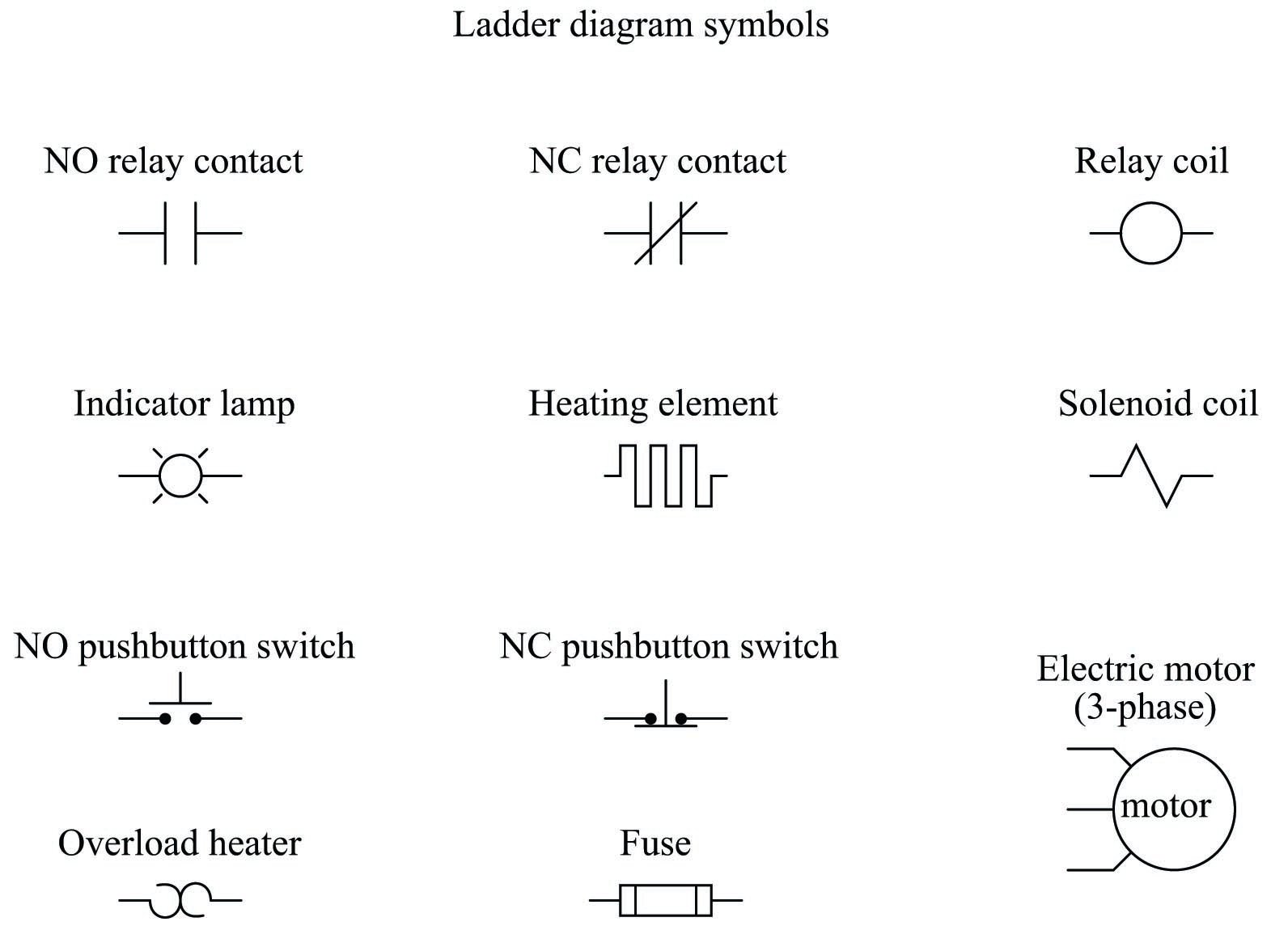
Relay Circuits And Ladder Diagrams Relay Control Systems Automation Textbook from control.com > basic diagram symbols > industrial control system diagram symbols. The wpf diagram control provides a gallery of reusable symbols and diagram elements, called a let's see how to create a stencil with our network diagram symbols. All circuit symbols are in standard format and they are mostly used to draw a circuit diagram and are standardized internationally by the ieee. Ciircuits, diagrams & symbols includes: A circuit diagram (electrical diagram, elementary diagram, electronic schematic) is a graphical representation of an electrical circuit. While there are more than 30 symbols used in set theory , you don't need to memorize them all to get started. An activity diagram visually presents a series of actions and the flow of control in a system. Similarly, the verbiage in the text calls for surge and lightning protection.
While there are more than 30 symbols used in set theory , you don't need to memorize them all to get started.
Circuit symbols are used in circuit diagrams (schematics) to represent electronic components. Circuit symbols overview resistors capacitors inductors, coils, chokes & transformers diodes bipolar transistors field effect transistors wires, switches. Electrical & electronic symbols and images are used by engineers in circuit diagrams and schematics to show how a circuits components are connected together. These symbols help create accurate diagrams and documentation. P&id symbols for lines, valves, instruments, pumps, compressors, heat exchangers, vessels, columns a set of standardized p&id symbols is used by process engineers to draft such diagrams. At first glance, the repair diagram may not convey how the wires. Ciircuits, diagrams & symbols includes: The wpf diagram control provides a gallery of reusable symbols and diagram elements, called a let's see how to create a stencil with our network diagram symbols. > basic diagram symbols > industrial control system diagram symbols. Visual walkthrough of schematic diagram and control logic. These are used to represent the control systems in pictorial form. A flowchart is a type of diagram that represents an algorithm, workflow or process, showing the steps as boxes of various kinds, and their order by connecting them with arrows. Graphic symbols for distributed control/shared display instrumentation, logic and computer in attempting to implement these systems, the need for supplementary symbolism has become apparent.