Home
› Heat Pump Air Handler Wiring Diagram : Diagram Lennox Hvac Wiring Diagram Full Version Hd Quality Wiring Diagram Diagramrt Hosteria87 It / I preparation check that each tube(both liquid and gas side tubes) between the indoor and outdoor units has been properly.
Heat Pump Air Handler Wiring Diagram : Diagram Lennox Hvac Wiring Diagram Full Version Hd Quality Wiring Diagram Diagramrt Hosteria87 It / I preparation check that each tube(both liquid and gas side tubes) between the indoor and outdoor units has been properly.
Heat Pump Air Handler Wiring Diagram : Diagram Lennox Hvac Wiring Diagram Full Version Hd Quality Wiring Diagram Diagramrt Hosteria87 It / I preparation check that each tube(both liquid and gas side tubes) between the indoor and outdoor units has been properly.. Air handler with single speed cooling unit, 2 stage heat. View and download nordyne air conditioner / heat pump air handler owner's manual & installation instructions online. How an air handler & heat pump work & are controlled by 24v thermostat wires! O/bw2 y1 y2 heat pump. The fan, often called an air handler or blower, circulates air throughout the house.
How an air handler & heat pump work & are controlled by 24v thermostat wires! If u can send a email i would appreciate it 🙂. The circulation pump is factory installed within the air handler. I also need the the payne thermostat wiring in the wall there are two sets of. This wire is usually not connected to the indoor airhandler.
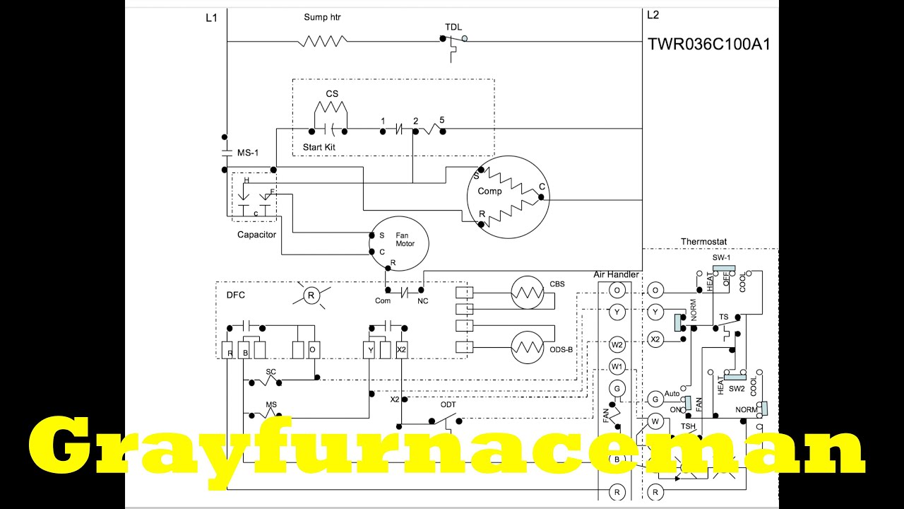
Heat Pump Thermostat Wiring Chart Diagram Easy Step By Step from highperformancehvac.com The basic heat pump wiring for a heat pump thermostat is illustrated here. Quick explanation of air handler wiring for heat pump. Air handler return air temperature the return air temperature entering the air handler is approx. As shown in the diagram, you the y terminal is where the signal to the cooling air conditioner signal is connected. Air handler (model american standard/train twe036c140b0) wiring diagram. Air to air heat pump, duel fuel system just started installing heat pumps hear in montana as a duel fuel system partnered with a gas furnace. Symbols that represent the constituents in the circuit, and lines that represent the connections bewteen barefoot and shoes. The outdoor unit will have its own diagram, but may not include the indoor air handler and will probably not include the thermostat.
This wire is usually not connected to the indoor airhandler.
As shown in the diagram, you the y terminal is where the signal to the cooling air conditioner signal is connected. The outdoor unit will have its own diagram, but may not include the indoor air handler and will probably not include the thermostat. Consult heat pump wiring guide. O/bw2 y1 y2 heat pump. This wire is usually not connected to the indoor airhandler. How an air handler & heat pump work & are controlled by 24v thermostat wires! It corresponds to the chart below to explain the thermostat terminal functions. Standard motor caf/air handler wiring diagram. Air handler with single speed cooling unit, 2 stage heat. If there is no current to the circulation pump, measure at the fuse and the relay card (see wiring diagram). The fan, often called an air handler or blower, circulates air throughout the house. Stage 2 compressor and auxiliary heat, if applicable. The diagram offers visual representation of an electric structure.
This diagram is to be used as reference for the low voltage control wiring of your heating and ac system. The circulation pump is factory installed within the air handler. Always refer to your thermostat or equipment installation guides to verify proper wiring. 1 these air handlers are ari certified with various split system air conditioners and heat pumps (ari standard 210/240). Standard motor caf/air handler wiring diagram.
The Heat Pump Wiring Diagram Overview Youtube from i.ytimg.com Consult heat pump wiring guide. Wiring diagrams include two things: Trane air handler wiring diagram cooling heat pump convertible air handlers cooling heat pump c. Standard motor caf/air handler wiring diagram. Do not jumper rc or rh. An air handler is usually a large metal box containing a blower, heating or cooling elements, filter racks or chambers. Connect low voltage control wiring to the low voltage terminal board located on the side of the fan control box per the typical interconnecting wiring diagrams on pages 13 through 22. The diagram offers visual representation of an electric structure.
.wiring diagrams for air conditioners, heat pumps, and heating equipment from a variety of free furnace, heat pump, air conditioner installation & service manuals, wiring diagrams, parts lists.
Unfortunately, the wiring diagrams for heat pumps are not so easy to come up with. As shown in the diagram, you the y terminal is where the signal to the cooling air conditioner signal is connected. I cant seem to get a whole diagram anywhere from heatpump to airhandler/furnace to thermostat. Wiring diagrams include two things: Trane air handler wiring diagram cooling heat pump convertible air handlers cooling heat pump c. 4 22 1774 01 0905 en model rated voltsphhz. Standard motor caf/air handler wiring diagram. The r wire needs to go into the rc terminal on your ecobee. A wiring diagram is a schematic which uses abstract pictorial symbols to show all the interconnections of components in a very system. How to read a heat pump wiring diagram! As you can see drawing and translating rheem heat pump wiring diagram can be a complicated undertaking on itself. How an air handler & heat pump work & are controlled by 24v thermostat wires! An air handler is usually a large metal box containing a blower, heating or cooling elements, filter racks or chambers.
As shown in the diagram, you the y terminal is where the signal to the cooling air conditioner signal is connected. I preparation check that each tube(both liquid and gas side tubes) between the indoor and outdoor units has been properly. The outdoor unit will have its own diagram, but may not include the indoor air handler and will probably not include the thermostat. A wiring diagram is a schematic which uses abstract pictorial symbols to show all the interconnections of components in a very system. The electrical wiring diagrams for typical air conditioning equipment.
Bryant Heat Pump Thermostat Wiring Diagram On Hvac Capacitor Wiring Diagram Thermostat Wiring Heat Pump System Heat Pump from i.pinimg.com Carrier heat pump wiring diagram pipit www champion testen de goodman teles york help doityourself com community forums bb087e ecobee3 library thermostat chart easy step by evcon diagrams nh 0191 handler diagramshtml air carrier heat pump wiring diagram pipit www champion testen de. This wire is usually not connected to the indoor airhandler. Technical documentation | air and ground source heat pumps. This terminal will call for the need to cool the room when the set temperature is lower than the room temperature. Connect low voltage control wiring to the low voltage terminal board located on the side of the fan control box per the typical interconnecting wiring diagrams on pages 13 through 22. As you can see drawing and translating rheem heat pump wiring diagram can be a complicated undertaking on itself. If u can send a email i would appreciate it 🙂. The circulation pump is factory installed within the air handler.
Standard motor caf/air handler wiring diagram.
Air handler with single speed cooling unit, 2 stage heat. 1916, produces air curtains, air handlers, dehumidifiers, direct vent lp gas and natural gas furnaces. If u can send a email i would appreciate it 🙂. Technical documentation | air and ground source heat pumps. The electrical wiring diagrams for typical air conditioning equipment. It corresponds to the chart below to explain the thermostat terminal functions. The air handler is universal for cooling only, electric heat or heat pumps which is why they show running so many conductors to the thermostat. O/bw2 y1 y2 heat pump. 1)air purging with a vacuum pump. Refer to the split system outdoor unit product data guides for performance data. The diagram offers visual representation of an electric structure. .wiring diagrams for air conditioners, heat pumps, and heating equipment from a variety of free furnace, heat pump, air conditioner installation & service manuals, wiring diagrams, parts lists. Always refer to your thermostat or equipment installation guides to verify proper wiring.