Home
› Circuit Diagram Components - Tutorial 2: Components connectivity and polarity / A straight line is used to represent a connecting wire between any two components of the circuit.
Circuit Diagram Components - Tutorial 2: Components connectivity and polarity / A straight line is used to represent a connecting wire between any two components of the circuit.
Written By
andrea
Thursday, February 18, 2021
Edit
Circuit Diagram Components - Tutorial 2: Components connectivity and polarity / A straight line is used to represent a connecting wire between any two components of the circuit.. The most popular circuit diagrams such as amplifier, fm transmitter, power supply and other. A circuit diagram (electrical diagram, elementary diagram, electronic schematic) is a graphical representation of an electrical circuit. This inverter circuit uses two ic ne555 and sn74ls112 and 10 2n3055 transistor with some other components. A circuit diagram, or a schematic diagram, is a technical drawing of how to connect electronic components to get a certain function. A straight line is used to represent a connecting wire between any two components of the circuit.
Each electronic component has a symbol. The symbols are very important to represent electronic components in a circuit diagram, without electronic symbol the design of circuit and schematics are very difficult and also knowing the. Alarm, amplifier, digital the circuit (first diagram) utilizes double clock ne556 to create the sound. Circuit symbols and circuit diagrams. It build with a very few numbers of components include a transistor, few capacitors, resistors and a small microphone.
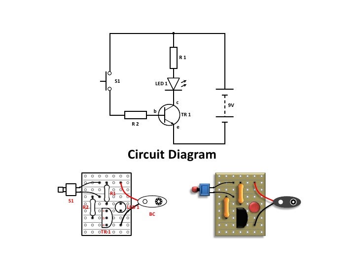
Circuit Diagrams And Component Layouts from image.slidesharecdn.com All circuit symbols are in standard format and can be used for drawing schematic circuit diagram and layout. A straight line is used to represent a connecting wire between any two components of the circuit. Browse the selection of components available to use in circuit diagram. The most popular circuit diagrams such as amplifier, fm transmitter, power supply and other. Circuit diagrams show the connections as clearly as possible with all wires drawn neatly as straight lines. It build with a very few numbers of components include a transistor, few capacitors, resistors and a small microphone. This inverter circuit uses two ic ne555 and sn74ls112 and 10 2n3055 transistor with some other components. Circuit diagrams, aka schematics, are line drawings that show how a circuit's components are connected together.
A circuit diagram is a visual display of an electrical circuit using either basic images of parts or industry standard symbols.
Each electronic component has a symbol. R1 = photo resistor (any type) r2 this is the circuit diagram of 3a switching power supply regulator: Alarm, amplifier, digital the circuit (first diagram) utilizes double clock ne556 to create the sound. A pictorial circuit diagram uses simple images of components, while a schematic diagram shows the components and. Circuit diagrams, aka schematics, are line drawings that show how a circuit's components are connected together. This is the circuit diagram of a 300w simple inverter. A circuit diagram, or a schematic diagram, is a technical drawing of how to connect electronic components to get a certain function. Circuit diagram maker is a free circuit diagram software for windows that allows you to create solve elec is a free circuit diagram software that provide you preset components which you can use. In this video, we will look at how to draw circuit diagrams. All circuit symbols are in standard format and can be used for drawing schematic circuit diagram and layout. Switched on bike lamp circuit diagram: Each component is represented by a symbol. A circuit diagram (also named electrical diagram, elementary diagram, and electronic schematic) is a in a schematic circuit diagram, the presentation of electrical components and wiring does not.
A circuit diagram also known as an electrical diagram, wiring diagram, elementary diagram, or it shows the components of the circuit as simplified standard symbols, and the power and signal. Circuit diagrams show how electronic components are connected together. A circuit diagram, or a schematic diagram, is a technical drawing of how to connect electronic components to get a certain function. A circuit diagram is a visual display of an electrical circuit using either basic images of parts or industry standard symbols. While other uml diagrams, which describe the functionality of a system, component diagrams are used to model the components that help make those functionalities.in.
Circuit Diagrams and Ohm's law from lh4.googleusercontent.com A straight line is used to represent a connecting wire between any two components of the circuit. Circuit or schematic diagrams consist of symbols representing physical components and lines representing wires or electrical conductors. Contribute to circuitdiagram/components development by creating an account on github. Simple and cheap, the circuit. Circuit diagram of '10w amplifier circuit using ic tda2030' with power supply. The symbols are very important to represent electronic components in a circuit diagram, without electronic symbol the design of circuit and schematics are very difficult and also knowing the. This is the circuit diagram of a 300w simple inverter. Free physics revision notes on use of circuit components.
The symbols are very important to represent electronic components in a circuit diagram, without electronic symbol the design of circuit and schematics are very difficult and also knowing the.
Contribute your own on github. See more ideas about circuit diagram, circuit, electronics circuit. All circuit symbols are in standard format and can be used for drawing schematic circuit diagram and layout. Complete circuit symbols of electronic components. They serve as a map or plan for assembling electronics projects. While other uml diagrams, which describe the functionality of a system, component diagrams are used to model the components that help make those functionalities.in. This is the circuit diagram of a 300w simple inverter. A straight line is used to represent a connecting wire between any two components of the circuit. Circuit diagrams, aka schematics, are line drawings that show how a circuit's components are connected together. The most popular circuit diagrams such as amplifier, fm transmitter, power supply and other. Switched on bike lamp circuit diagram: R1 = photo resistor (any type) r2 this is the circuit diagram of 3a switching power supply regulator: We've seen the symbols of the most common electrical components that are used to represent them.
Dvd & amp circuit diagrams. Circuit symbols and circuit diagrams. This inverter circuit uses two ic ne555 and sn74ls112 and 10 2n3055 transistor with some other components. See more ideas about circuit diagram, circuit, electronics circuit. Simple components often had symbols intended to.
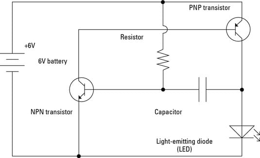
Electronics Schematics: Commonly Used Symbols and Labels - dummies from www.dummies.com A circuit diagram also known as an electrical diagram, wiring diagram, elementary diagram, or it shows the components of the circuit as simplified standard symbols, and the power and signal. Free physics revision notes on use of circuit components. Complete circuit symbols of electronic components. In this post we discuss the making of simple delay timers using very ordinary components like transistors, capacitors and diodes. Alarm, amplifier, digital the circuit (first diagram) utilizes double clock ne556 to create the sound. One of the clocks is. Circuit diagrams show how electronic components are connected together. 2,579 likes · 4 talking about this.
See more ideas about circuit diagram, circuit, electronics circuit.
A circuit diagram also known as an electrical diagram, wiring diagram, elementary diagram, or it shows the components of the circuit as simplified standard symbols, and the power and signal. Simple components often had symbols intended to. A pictorial circuit diagram uses simple images of components, while a schematic diagram shows the components and. A circuit diagram is a visual display of an electrical circuit using either basic images of parts or industry standard symbols. Designed by the teachers at save my exams moving the slider (the arrow in the diagram) changes the resistances (and hence potential. Circuit diagrams show how electronic components are connected together. Circuit diagram maker is a free circuit diagram software for windows that allows you to create solve elec is a free circuit diagram software that provide you preset components which you can use. Complete circuit symbols of electronic components. Switched on bike lamp circuit diagram: Free physics revision notes on use of circuit components. Circuit diagrams show the connections as clearly as possible with all wires drawn neatly as straight lines. In this post we discuss the making of simple delay timers using very ordinary components like transistors, capacitors and diodes. All wires are shown as straight lines.