Home
› Wiring A Switch Leg - Need A Wire Diagram To Understand This Doityourself Com Community Forums : 3 way switch wiring diagram part 2 3way switch wiring diagrams #4, #5 and #6
Wiring A Switch Leg - Need A Wire Diagram To Understand This Doityourself Com Community Forums : 3 way switch wiring diagram part 2 3way switch wiring diagrams #4, #5 and #6
Wiring A Switch Leg - Need A Wire Diagram To Understand This Doityourself Com Community Forums : 3 way switch wiring diagram part 2 3way switch wiring diagrams #4, #5 and #6. The switch leg brings power to the fixture when the switch is turned on. Level beginner description power (a hot and a neutral) is fed to the switch with 1 switch leg run from the switch to 1 light. Power to switch, then to light or lights. Either 14/2 with ground (wg) for 15 amp circuits or 12/2wg for 20 amp circuits. Consequently it is quite common to find a white wire in a switch box that is the hot line and the black wire is the switch leg connected to the load.
This is commonly used to turn a table lamp on and off when entering a room. The source neutral wire on the receptacle is removed and spliced to the white wire running to the switch and to a pigtail back to the receptacle neutral. Wiring a switch to a wall outlet. Connect the wire marked common to the black or dark colored screw. When the switch is on, the switched leg then provides power to the fixture or device to be powered.
3 Way Switch Wiring Methods Electrician 101 from docs.google.com 3 way switch wiring diagram part 2 3way switch wiring diagrams #4, #5 and #6 Instead of running a separate pigtail from the hot wire to each switch, just leave the hot wire extra long. You cannot connect a receptacle outlet to this type of switch wiring because there is no neutral wire in the switch box, but you can at the ceiling electrical box, assuming there is enough room. How to wire a light switch learning how to wire a light switch is one of the basic skills that every homeowner should do. With this, the hot wire initially bypasses the fixture, then loops through the switch and back to the fixture. When wiring switches, this type of cable may be used as a switch leg—where you need two black wires to go from the switch to black wires located at the light or at an intermediate electrical box. As a homeowner, you will likely need to replace a light switch many times and paying an electrician is not optimal when you can do it in just a few minutes. Dawson notes that red wires are commonly used when installing ceiling fans that use separate switches for the fan motor and light.
The source neutral wire on the receptacle is removed and spliced to the white wire running to the switch and to a pigtail back to the receptacle neutral.
How to wire a light switch learning how to wire a light switch is one of the basic skills that every homeowner should do. The extra connections in this method mean you have to. Outlet wiring for a table lamp or a floor light fixture. With this, the hot wire initially bypasses the fixture, then loops through the switch and back to the fixture. When wiring switches, this type of cable may be used as a switch leg—where you need two black wires to go from the switch to black wires located at the light or at an intermediate electrical box. To connect the switches, simply score the wire with your wire stripper and push the insulation to expose about 3/4 in. Like black wires, red wires can be used as switch legs. What is a switch leg? In the wiring diagram below the white wire that goes to the switch is being used as the hot conductor, not as a neutral. These electrical wiring diagrams show typical connections. You cannot connect a receptacle outlet to this type of switch wiring because there is no neutral wire in the switch box, but you can at the ceiling electrical box, assuming there is enough room. The diagram below shows the power entering the circuit at the grounded outlet box location, then sending power up to the switch and a switched leg back down to the outlet. Two common methods for wiring a light switch.
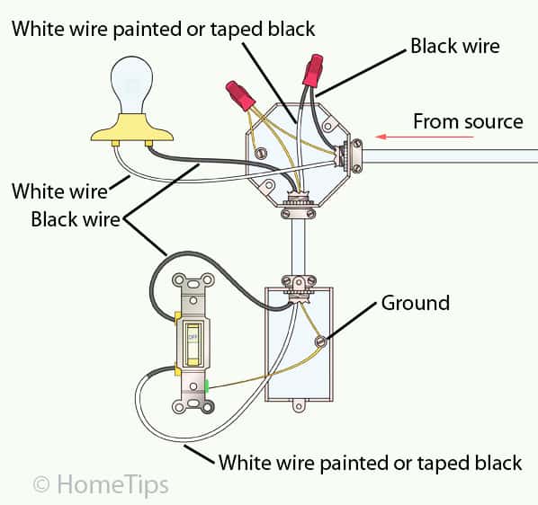
As shown in the diagrams below, you can paint a couple of inches of the end of the white wire black—or wrap it with black electrical tape—to. When wiring switches, this type of cable may be used as a switch leg—where you need two black wires to go from the switch to black wires located at the light or at an intermediate electrical box. Mark both ends of this wire by wrapping it with black electrical tape to alert others working on the circuit later that it is no longer neutral. Do you have a switch leg? Outlet wiring for a table lamp or a floor light fixture.
3 Way Switch Wiring Methods 2 Wire And Light Fed S3 from docs.google.com Connect the wire marked common to the black or dark colored screw. At the switch, the neutral wire is capped unless needed to power a smart switch such as a new dimmer. When this is the case, the hot black wire is connected to one switch to operate the fan motor, and the hot red wire is connected to another switch to operate. Wiring a switch to a wall outlet. This shows wiring a light switch when the power comes into the light outlet first. The source is at sw1 and the hot wire is connected to one of the terminals there. This article explains the two most common methods for wiring a basic light switch: In the wiring diagram below the white wire that goes to the switch is being used as the hot conductor, not as a neutral.
The source neutral wire on the receptacle is removed and spliced to the white wire running to the switch and to a pigtail back to the receptacle neutral.
With this, the hot wire initially bypasses the fixture, then loops through the switch and back to the fixture. The black wire from the switch connects to the hot on the receptacle. Connect the ground wire to the green screw. This shows wiring a light switch when the power comes into the light outlet first. Level beginner description power (a hot and a neutral) is fed to the switch with 1 switch leg run from the switch to 1 light. Dawson notes that red wires are commonly used when installing ceiling fans that use separate switches for the fan motor and light. The switch leg is controlling the bottom half of each split receptacle outlet. In the wiring diagram below the white wire that goes to the switch is being used as the hot conductor, not as a neutral. Three wires will be attached to your switch: The black and white wires are attached using brass screws (image 1); One 3 wire cable originates at the first switch box and has its white insulated wire as a neutral. The source neutral wire on the receptacle is removed and spliced to the white wire running to the switch and to a pigtail back to the receptacle neutral. What is a switch leg?
A hot (black) wire, a neutral (white) wire and a ground (copper) wire. The source neutral wire on the receptacle is removed and spliced to the white wire running to the switch and to a pigtail back to the receptacle neutral. This article explains the two most common methods for wiring a basic light switch: The switch leg brings power to the fixture when the switch is turned on. What i'm going to show you in this post is the easiest and (in my humble opinion) the most streamlined way of wiring a switch to a light fixture.
Standard Single Pole Light Switch Wiring Hometips from www.hometips.com With this, the hot wire initially bypasses the fixture, then loops through the switch and back to the fixture. Instead of running a separate pigtail from the hot wire to each switch, just leave the hot wire extra long. When this is the case, the hot black wire is connected to one switch to operate the fan motor, and the hot red wire is connected to another switch to operate. Notice the 2 red wire nuts on the travelers in the wiring schematic below and compare that with no wire nuts on travelers in the methods above. Consequently it is quite common to find a white wire in a switch box that is the hot line and the black wire is the switch leg connected to the load. This is commonly used to turn a table lamp on and off when entering a room. In the wiring diagram below the white wire that goes to the switch is being used as the hot conductor, not as a neutral. A 2 wire feed is pulled from the nearest source of power like a receptacle or the panel to the switch.
You cannot connect a receptacle outlet to this type of switch wiring because there is no neutral wire in the switch box, but you can at the ceiling electrical box, assuming there is enough room.
In the wiring diagram below the white wire that goes to the switch is being used as the hot conductor, not as a neutral. 3 way switch wiring diagram part 2 3way switch wiring diagrams #4, #5 and #6 This article explains the two most common methods for wiring a basic light switch: One 3 wire cable originates at the first switch box and has its white insulated wire as a neutral. How to wire a light switch learning how to wire a light switch is one of the basic skills that every homeowner should do. The source neutral wire on the receptacle is removed and spliced to the white wire running to the switch and to a pigtail back to the receptacle neutral. These wiring diagrams help you identify the power feed and the switch leg leading to the fixture. As shown in the diagrams below, you can paint a couple of inches of the end of the white wire black—or wrap it with black electrical tape—to. 3way switch wiring diagrams #1, #2 and #3 the key to three way switch wiring depends on two main factors. Connect the ground wire to the green screw. Two common methods for wiring a light switch. At the switch, the neutral wire is capped unless needed to power a smart switch such as a new dimmer. The other 3 wire cable originates at the second switch box and will become the switch leg.