Hvac Ladder Diagram - Electrical Wiring Diagram Plc / Of the two types of.. Installation diagrams are not required if there is any repair work to be done. Types of wiring diagrams there are three basic types of wiring diagrams used in the hvac/r industrytoday. There are three basic types of wiring diagrams used in the hvac/r industry today, which are: They are the line diagram, the ladder diagram, and the installation diagram. Air conditioner wiring diagram pdf best hvac wiring diagram pdf.
Because it explains electrical circuits, the diagram looks like a ladder, which is where the name comes from. The first, and most common, is the ladder diagram. I have to include compressor running capacitor, compressor, safety thermostat, thermostat terminal board, transformer, thermostat, reversing valve, solenoid, outdoor, fan motor capacitor, outdoor fan motor, high pressure switch, low pressure switch, indoor fan. To keep track of wiring, hvac technicians rely on circuit schematics or visual representations of wiring programs. Connecting all of the electrical components together is the electric wiring.
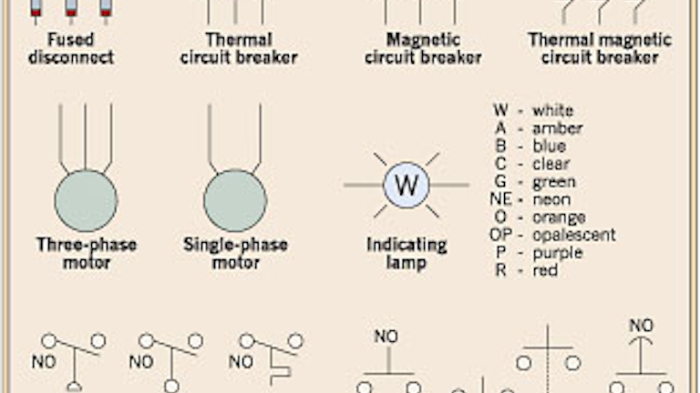
Electrical Ladder Drawing Basics Ec M from base.imgix.net Electrical ladder drawings are still one of the common and reliable tools used to troubleshoot equipment when it fails. The first and most common is the ladder diagram, so called because it looks like the symbols that are used to represent the components in the system have been placed on the rungs of a ladder. Most ladder diagrams show the following basic components: Schematic and ladder diagrams wiring diagrams for hvac systems and other complicated electrical systems come in two major variations — schematic diagrams and ladder diagrams. They are the line diagram, the ladder diagram, and the installation diagram. Ladder diagrams will be referred to as schematic. A ladder diagram, shown in figure 3, is a diagram that explains the logic of the electrical circuit or system using standard nema or iec symbols. Ladder diagrams are specialized schematics commonly used to document industrial control logic systems.
Along each side you find connections.
Example of a simple wiring diagram how to construct diagrams sketch or schematic ladder logic what is plc understanding electrical drawings and relay heating circuits hvac the for factory air conditioning diffe types symbols motors control special motor edrawmax online engineer on disk basic program following circuit latch. Horizontal lines in a ladder diagram are called rungs, each one representing a unique parallel circuit branch between the poles of the power supply. Wiring diagram for trane air conditioner inspirational i have a. There will be lots of weeping and gnashing of teeth. Typically, wires in control systems are marked with numbers and/or letters for identification. Wiring diagram ac gas new wiring diagram indoor ac fresh air. As with any good troubleshooting tool, one must be familiar with its basic features to make the most of the diagram in the field. Along each side you find connections. Electrical ladder drawings are still one of the common and reliable tools used to troubleshoot equipment when it fails. Ladder diagram example a manual mixing operation is to be automated using sequential process control methods. Air conditioner wiring diagram pdf best hvac wiring diagram pdf. Installation diagrams are not required if there is any repair work to be done. By simply looking from left to right, you are able to trace the required power for the device.
From this point forward, ladder diagrams will be referred to as schematic diagrams, or schematics. a typical schematic of a packaged air conditioner is shown in figure 1. Bryan covers more electrical basics, 240v circuits, 120v and 24v with the differences between l1, l2, neutral, common and ground for hvac/r and an introducti. Finally, the illustration below is for a system with a single transformer. I am taking a course and have an assignment. The process composed of three steps:
Direct Digital Control Systems Tempcon Hvac Direct Digital Control Pneumatic Training Seminars from tempconinc.com I have to make a ladder diagram of a heat pump package air conditioning system. After explaining basic ladder diagrams and showing several examples ask the students to draw a simple diagram of a packages air conditioning unit without looking at an example. A ladder diagram, shown in figure 3, is a diagram that explains the logic of the electrical circuit or system using standard nema or iec symbols. Line diagrams are meant for professionals to understand. Because it explains electrical circuits, the diagram looks like a ladder, which is where the name comes from. Along each side you find connections. Think of a ladder's two rails as being an electrical supply (hot and neutral) going into a system. Where the power supply is, what path the power takes, the load component, the switch component, and a legend for the symbols used in the diagram.
From this point forward, ladder diagrams will be referred to as schematic diagrams, or schematics. a typical schematic of a packaged air conditioner is shown in figure 1.
You don't want a copy of the book; A ladder diagram, shown in figure 3, is a diagram that explains the logic of the electrical circuit or system using standard nema or iec symbols. The first and most common is the ladder diagram, so called because it looks like the symbols that are used to represent the components in the system have been placed on the rungs of a ladder. There are three basic types of wiring diagrams used in the hvacr industry today. There are three basic types of wiring diagrams used in the hvac/r industry today, which are: Using this software, you can easily create a ladder diagram. It consists of two wires drawn parallel and representing the main power source. I have to make a ladder diagram of a heat pump package air conditioning system. Along each side you find connections. I have to include compressor running capacitor, compressor, safety thermostat, thermostat terminal board, transformer, thermostat, reversing valve, solenoid, outdoor, fan motor capacitor, outdoor fan motor, high pressure switch, low pressure switch, indoor fan. Schematic and ladder diagrams wiring diagrams for hvac systems and other complicated electrical systems come in two major variations — schematic diagrams and ladder diagrams. Ladder diagram example a manual mixing operation is to be automated using sequential process control methods. Ladder diagram is a conventional form of programming the programmable logic controllers (plcs).
Types of wiring diagrams there are three basic types of wiring diagrams used in the hvac/r industrytoday. Electrical ladder drawings are still one of the common and reliable tools used to troubleshoot equipment when it fails. Along each side you find connections. There are three basic types of wiring diagrams used in the hvac/r industry today, which are: Typically, wires in control systems are marked with numbers and/or letters for identification.
Hvac Talk Heating Air Refrigeration Discussion from hvac-talk.com There are three basic types of circuit schematics used in hvac today. From this point forward, ladder diagrams will be referred to as schematic diagrams, or schematics. a typical schematic of a packaged air conditioner is shown in figure 1. Ladder diagrams will be referred to as schematic. The process composed of three steps: Ladder diagram is a conventional form of programming the programmable logic controllers (plcs). The first, and most common, is the ladder diagram. Using this software, you can easily create a ladder diagram. Not just the ladder diagram, but a lot of different types of diagrams such as erd, network diagram, use case diagram, uml diagrams, etc., can also be created in it.to deal with different types of diagram, it provides various dedicated sections containing.
The process composed of three steps:
Of the two types of. Electrical ladder drawings are still one of the common and reliable tools used to troubleshoot equipment when it fails. Line diagrams are meant for professionals to understand. After explaining basic ladder diagrams and showing several examples ask the students to draw a simple diagram of a packages air conditioning unit without looking at an example. Installation diagrams are not required if there is any repair work to be done. Example of a simple wiring diagram how to construct diagrams sketch or schematic ladder logic what is plc understanding electrical drawings and relay heating circuits hvac the for factory air conditioning diffe types symbols motors control special motor edrawmax online engineer on disk basic program following circuit latch. I have to make a ladder diagram of a heat pump package air conditioning system. From this point forward, ladder diagrams will be referred to as schematic diagrams, or schematics. a typical schematic of a packaged air conditioner is shown in figure 1. The process composed of three steps: The ladder diagram makes it easier to see how these devices are wired. You don't want a copy of the book; Most units have ladder as well as line diagrams on them. Horizontal lines in a ladder diagram are called rungs, each one representing a unique parallel circuit branch between the poles of the power supply.