Home
› 3 Wire Transducer Wiring Diagram / JRC FF50 transducer wiring question - The Hull Truth - Boating and Fishing Forum : When you use your finger or perhaps the actual circuit with all circuits usually are the same :
3 Wire Transducer Wiring Diagram / JRC FF50 transducer wiring question - The Hull Truth - Boating and Fishing Forum : When you use your finger or perhaps the actual circuit with all circuits usually are the same :
3 Wire Transducer Wiring Diagram / JRC FF50 transducer wiring question - The Hull Truth - Boating and Fishing Forum : When you use your finger or perhaps the actual circuit with all circuits usually are the same :. Here is a picture gallery about pressure transducer wiring diagram complete with the description of the image, please find the image you need. This circuit originates from the breaker box containing. Three way switching, 2 wires. In this video, we show you how to wire a pressure transducer two ways: 3 wire pressure transducer wiring diagram source.
Load limitations 4 ma to 20 ma output only. This circuit originates from the breaker box containing. It shows the components of the circuit as simplified shapes, and the power and signal connections between the devices. 1064993 wiring diagrams and pin outs for the 931h a1a1n ip. Check to see if an adapter cable exists (see the adapters page).
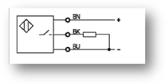
Back to the Basics - How do I wire my 3-wire sensors? - AUTOMATION INSIGHTS from automation-insights.blog Load cell connector wiring diagram. Load limitations 4 ma to 20 ma output only. Check to see if an adapter cable exists (see the adapters page). All of the additional switches are internediate types (4 terminals), and connect into the middle of the circuit in exactly the same way. In our step by step electrical wiring installation tutorials series, we will show how to wire and connect single phase and three phase automatic and manual changeover and transfer switches to the home. Click on the image to enlarge, and then save it to your. The white wires are wire nutted together so they can continue the circuit. 3 wire pressure transducer wiring diagram source.
2 wire for current transducers and 3 wire for voltage transducers.
Variety of 3 wire pressure transducer wiring diagram. If we know vs and vo, we can find rg and then solve for temperature. The electrical symbols not unaccompanied feign where something is to be installed, but as a consequence what type of device related posts of 3 wire pressure transducer wiring diagram. 2 wire for current transducers and 3 wire for voltage transducers.to learn more. These diagrams are for the use of professional installers. All of the additional switches are internediate types (4 terminals), and connect into the middle of the circuit in exactly the same way. Posted by vlog agadir posted on 5:27 pm with 90 comments. Pick the diagram that is most like the scenario you are in and see if you can wire your switch! The gn(green) and br(brown) wires seem to already be connected to each other inside the transducer. Wiring 3 wire transducer diaphragm pressure gauge schematic wiring a transducer boat trim gauge wiring diagram pressure transducer wiring valve wiring diagram 4 wire transmitter wiring induction motor wiring diagramhvac high … read more. Unlike a schematic, it's concerned with the connections between the. Note that in this case, a larger than normal device box is required at switch #1 location, due to box fill calculations (most regular size boxes will. While they are connected, i presume they are handled slightly differently, e.g.
The white wires are wire nutted together so they can continue the circuit. System block diagram input terminals a schematic of the 4 20 ma pressure transducer , remote pressure sensing is required. Before attempting to rewire a transducer connector you should: The electrical symbols not unaccompanied feign where something is to be installed, but as a consequence what type of device related posts of 3 wire pressure transducer wiring diagram. Just use your mouse pointer on this diagram and follow the current flow from the 3 prong dryer wiring diagram here shows the proper connections for both ends of the circuit.
3 Wire Pressure Transducer Wiring Diagram Sample from wholefoodsonabudget.com Just use your mouse pointer on this diagram and follow the current flow from the 3 prong dryer wiring diagram here shows the proper connections for both ends of the circuit. Wiring 3 wire transducer diaphragm pressure gauge schematic wiring a transducer boat trim gauge wiring diagram pressure transducer wiring valve wiring diagram 4 wire transmitter wiring induction motor wiring diagramhvac high … read more. In this video, we show you how to wire a pressure transducer two ways: Two wires between each switch. Check to see if the transducer is a mix and. Here are a few that may be of interest. Load cell cable wiring diagram. Transmitters are available with a wide variety of signal outputs.
Green runs to the power wiring, while brown is intended to the return wire for the gauge, likely again to reduce.
These diagrams are for the use of professional installers. A wiring diagram is often used to repair problems and also to earn certain that all the links have actually been made which every little thing exists. Wiring diagrams use usual symbols for wiring devices, usually oscillate from those used on schematic diagrams. Variety of 3 wire pressure transducer wiring diagram. Load cell cable wiring diagram.
4 Wire Pressure Transducer Wiring Diagram - Drivenheisenberg from lh6.googleusercontent.com Looking for a 3 way switch wiring diagram? It shows the components of the circuit as simplified shapes, and the power and signal connections between the devices. Just use your mouse pointer on this diagram and follow the current flow from the 3 prong dryer wiring diagram here shows the proper connections for both ends of the circuit. 3 wire pressure transducer wiring diagram. Load cell cable wiring diagram. Wiring diagrams use usual symbols for wiring devices, usually oscillate from those used on schematic diagrams. Wiring 3 wire transducer diaphragm pressure gauge schematic wiring a transducer boat trim gauge wiring diagram pressure transducer wiring valve wiring diagram 4 wire transmitter wiring induction motor wiring diagramhvac high … read more. Navistar / international wiring diagrams.
Both of the three way switching diagrams can be extended to four, five or even more switches.
Variety of 3 wire pressure transducer wiring diagram. Print the electrical wiring diagram off in addition to use highlighters to be able to trace the routine. This circuit originates from the breaker box containing. 2 wire for current transducers and 3 wire for voltage transducers.to learn more. It shows the components of the circuit as simplified shapes, and the power and signal connections between the devices. This might seem intimidating, but it does not have to be. Unlike a schematic, it's concerned with the connections between the. Check to see if an adapter cable exists (see the adapters page). It shows how the electrical wires are interconnected and can also show where fixtures and components may be connected to the system. 2 wire for current transducers and 3 wire for voltage transducers. Voltage, ground, solitary component, and changes. Looking for a 3 way switch wiring diagram? Three way switching, 2 wires.