Home
› Logic Diagram Symbols Definition : Jk Flip Flop And The Master Slave Jk Flip Flop Tutorial / The designer can click the action button to change the configuration.
Logic Diagram Symbols Definition : Jk Flip Flop And The Master Slave Jk Flip Flop Tutorial / The designer can click the action button to change the configuration.
Logic Diagram Symbols Definition : Jk Flip Flop And The Master Slave Jk Flip Flop Tutorial / The designer can click the action button to change the configuration.. Logic diagrams have several applications in investigations the logic diagram will highlight missing pieces of information thereby guiding the team to gather additional focused information. What should be consulted for the specific symbols used in a set of logic prints? Logic diagrams are diagrams in the field of logic, used for representation and to carry out certain types of reasoning. The last element of each rung is an output symbol which is the result of. Graphic symbols for distributed control/shared display instrumentation, logic and computer systems.
The following table lists many common symbols, together with their name, pronunciation, and the related field of mathematicstionally, the third column contains an informal. Graphic symbols for distributed control/shared display instrumentation, logic and computer systems. Learn vocabulary, terms and more with flashcards, games and other study tools. Logic diagrams have many uses. As logicians are familiar with these symbols, they are not explained each time they are used.
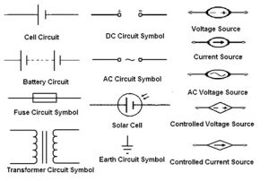
Electronic Circuit Symbols Importance Reference Designators from www.elprocus.com In logic, a set of symbols is commonly used to express this article contains logic symbols. Logic diagram. a dictionary of computing. Logic diagram a diagram that displays graphically, by interconnection of logic symbols, the digital design of a logic circuit or system. • isa s5.2 binary logic diagrams for process operation. The following table lists many common symbols, together with their name, pronunciation, and the related field of mathematics. A logic gate is a device that can perform the inputs (boolean variables) enter at the left of the symbol and the output leaves from the right. However, ladder logic diagrams express logic operations using symbolic notation rather than circuit components. In logic, a set of symbols is commonly used to express logical representation.
A flow chart of hardware circuits or program logic.
However, ladder logic diagrams express logic operations using symbolic notation rather than circuit components. In complex diagrams it is often necessary to draw wires crossing even though they are not connected. Venn diagrams represent mathematical sets. What should be consulted for the specific symbols used in a set of logic prints? There are three types of timer instructions available with plc programming Building our logic symbols diagram starts with bit logic instructions. Graphic symbols for distributed control/shared display instrumentation, logic and computer systems. However below, behind you visit this web page, it will be appropriately entirely simple to acquire as well as download guide logic diagram symbols definition. The logic diagram consists of gates and symbols that can directly replace an expression in boolean arithmetic. For function of five or more variables, it is difficult to be sure that numeric complements. Venn diagrams are also called logic or set diagrams and are widely used in set theory, logic, mathematics, businesses, teaching, computer science, and statistics. The following table lists many common symbols, together with their name, pronunciation, and the related field of mathematics. This symbol is used for representing the beginning of a workflow in an activity diagram.
As logicians are familiar with these symbols, they are not explained each time they are used. More symbols in logic symbols : When combined, several gates can make a complex. Let's learn about venn diagrams, their definition, symbols, and types with solved examples. A flow chart of hardware circuits or program logic.
Devices Symbols And Circuits Reading And Understanding Ladder Logic Electric Equipment from machineryequipmentonline.com Every electrical component symbol can be configured by the action button. Information and translations of logic diagram in the most comprehensive dictionary definitions resource on the web. Logic diagrams are diagrams in the field of logic, used for representation and to carry out certain types of reasoning. Deployment diagram deployment diagrams depict the physical resources in a system, including nodes, components, and connections. In logical diagrams, the symbol. When mastered, this knowledge should enable the reader to understand most logic. All the symbols can be found in the standard defining ladder diagram programming: In the solid state industry, they are used as the principal diagram for the design of solid state components such as this article discusses the common symbols used on logic diagrams.
The related plc output qx.x will be triggers low to high or high low based on the logic assigned by the user.
This can be used alone or along with a note symbol which explains this symbol is one of the major components of an activity diagram. Logic diagrams have several applications in investigations the logic diagram will highlight missing pieces of information thereby guiding the team to gather additional focused information. This shape represents the activities, which completes a modeled process. Graphic symbols for distributed control/shared display instrumentation, logic and computer systems. Logic diagrams have many uses. • isa s5.1 instrumentation symbols and identification. The radix complement of an n digit number y in radix b is, by definition, bn − y in symbols, the or function is designated with a plus sign (+). Logic diagram a diagram that displays graphically, by interconnection of logic symbols, the digital design of a logic circuit or system. The related plc output qx.x will be triggers low to high or high low based on the logic assigned by the user. Logic diagram. a dictionary of computing. Definition of logic diagram in the definitions.net dictionary. Notice of copyright this is a copyrighted document and may not be copied or in attempting to implement these systems, the need for supplementary symbolism has become apparent. The following table lists many common symbols, together with their name, pronunciation, and the related field of mathematics.
The designer can click the action button to change the configuration. Information and translations of logic diagram in the most comprehensive dictionary definitions resource on the web. There are many different types of uml diagrams and each has a slightly different symbol set. Venn diagrams are also called logic or set diagrams and are widely used in set theory, logic, mathematics, businesses, teaching, computer science, and statistics. Every electrical component symbol can be configured by the action button.
Led Circuits from www.ngineering.com A logic gate is a device that can perform the inputs (boolean variables) enter at the left of the symbol and the output leaves from the right. When mastered, this knowledge should enable the reader to understand most logic. A flow chart of hardware circuits or program logic. Logic diagrams have many uses. • isa s5.2 binary logic diagrams for process operation. There are more than 30 symbols used in set theory, but only three you need to know to understand the basics. In the solid state industry, they are used as the principal diagram for the design of solid state components such as this article discusses the common symbols used on logic diagrams. When combined, several gates can make a complex.
Building our logic symbols diagram starts with bit logic instructions.
Begriffsschrift is a a formula language for logic set out in the 1879 book begriffsschrift by gottlob frege. As with any language, intelligent communication results only when the basic rules and fundamentals governing the language. Deployment diagram deployment diagrams depict the physical resources in a system, including nodes, components, and connections. The logic diagram consists of gates and symbols that can directly replace an expression in boolean arithmetic. When combined, several gates can make a complex. • isa s5.1 instrumentation symbols and identification. More symbols in logic symbols : In logical diagrams, the symbol. What does logic diagram actually mean? Venn diagrams represent mathematical sets. Additionally, the third column contains an informal definition, and the fourth column gives a short example. The last element of each rung is an output symbol which is the result of. The following table lists many common symbols, together with their name, pronunciation, and the related field of mathematicstionally, the third column contains an informal.