41 Mux Logic Diagram / Multiplexer(MUX) and Multiplexing / The implementation of not gate is done using n selection lines.. Download scientific diagram | (a) schematic representation of 4:1 mux (b) qca majority logic diagram (c) the qca layout (d) simulation results. Digital and analog reasoning, circuit and also electrical wiring schematics as well as representations; Ladder logic diagram of 4 to 1 mux is given by Free download epubdiagram diagram of 2. Mux41 datasheet, cross reference, circuit and application notes in pdf format.
Vhdl tutorial behavioral vhdl 4 to 1 mux library ieee; Multiplexer mux and multiplexing tutorial. All the standard logic gates can be implemented with multiplexers. Mux41 datasheet, cross reference, circuit and application notes in pdf format. In this example, we will implement a full adder as a full adder has 3 input variables.
Digital Electronics - Multiplexers and De-multiplexers - EXAMRADAR from examradar.com Multiplexers different ways to implement verilog by examples. 214 14.3 an example of a. This is the diagram of logic diagram of 2 1 mux that you search. Schematic diagram of multiplexer using logic gates boolean functions using 2 to 1 multiplexer 4 to 1 multiplexer & truth table? And the error messages tell you exactly what is wrong. Logic diagrams are diagrams in the field of logic, used for representation and to carry out certain types of reasoning. As you can see clearly a multiplexer logic diagram simply consists of 2 not gates, 4 and gates, and 1 or gate. In this example, we will implement a full adder as a full adder has 3 input variables.
Becker 3.5m series logic board & wiring diagram.
We have to select 2 multiplexer. We can analyze it y = x'.1 + x.0 = x' it is not gate using 2:1 mux. Simple and efficient in terms of area and timing. Mux41 datasheet, cross reference, circuit and application notes in pdf format. And the error messages tell you exactly what is wrong. The implementation of not gate is done using n selection lines. Mux and decoders are called universal logic. Proj 43 floating point fused add subtract and multiplier units. 4 1 mux graphical symbol a truth table b download. Generally, design layouts consist of electrical schematics; The pass transistor design reduces the figure 3.7: That is, show the port map for each of the components shown in fig 2. In this post, we will see haw a 2:1 mux can be used to create different logic gates.
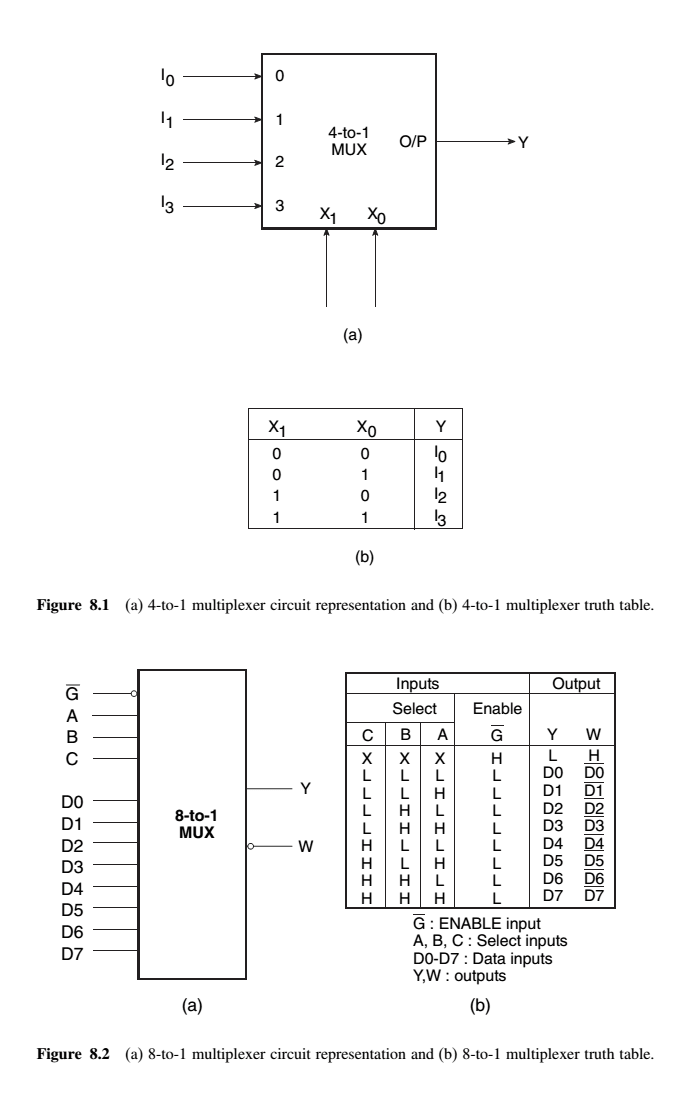
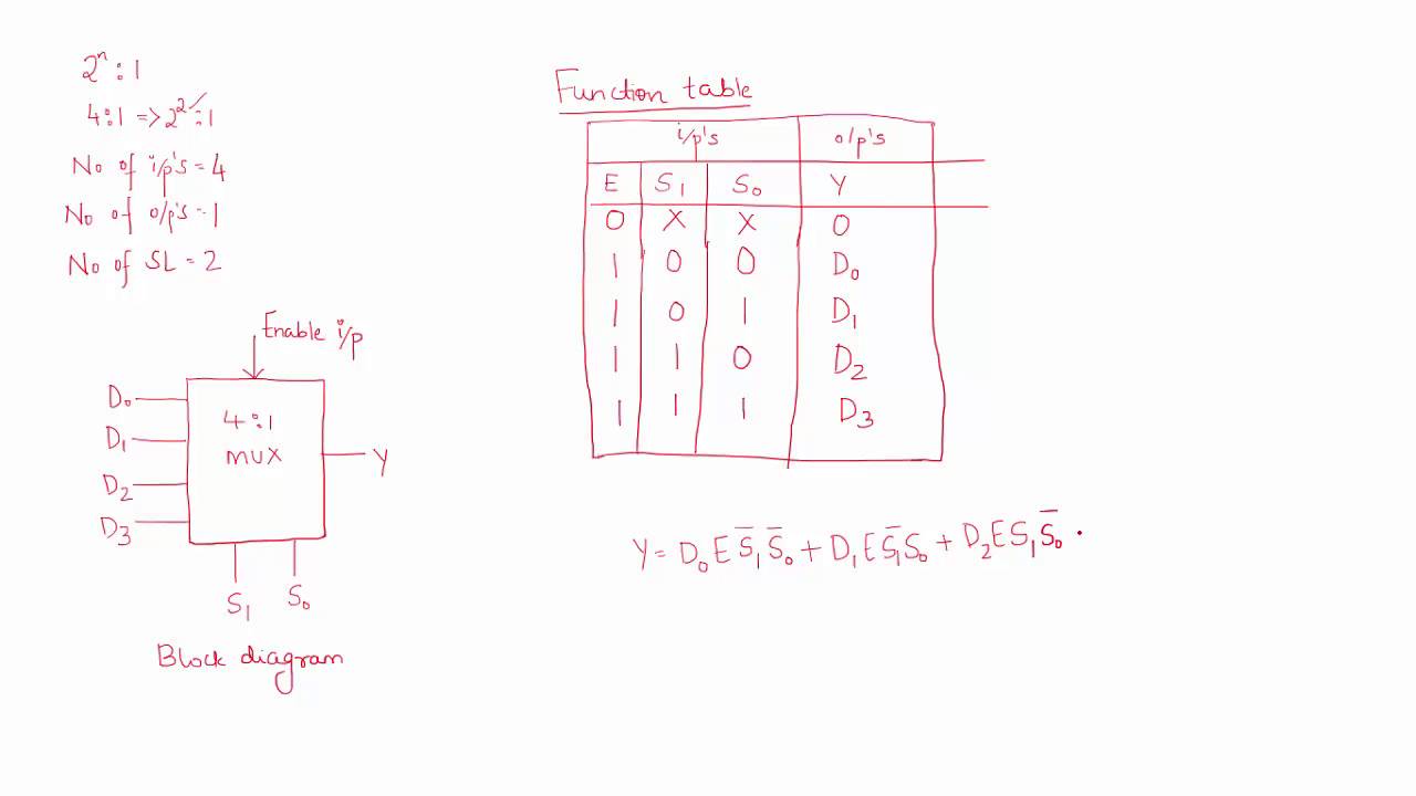
Figure 3.2.4 4:1 multiplexer verilog program multiplexers 2:1 mux structural model module mux21str(i0,i1,s,y) 41. In this post, i will tell you what is multiplexer (mux) and i am also will tell you about its working with logic diagram and uses. And the error messages tell you exactly what is wrong. In std_logic_vector(1 downto 0) proj 41 discrete wavelet transform (dwt) for image compression. Entity mux4_1 is port (c, d, e, f :
4 to 1 multiplexer - YouTube from i.ytimg.com Free download epubdiagram diagram of 2. All the standard logic gates can be implemented with multiplexers. In this post, we will see haw a 2:1 mux can be used to create different logic gates. Logic diagrams are diagrams in the field of logic, used for representation and to carry out certain types of reasoning. Ladder logic diagram of 4 to 1 mux is given by The lpm_mux, mux, and busmux megafunctions are available for all altera devices. Its truth table and circuit diagram is given by: Proj 43 floating point fused add subtract and multiplier units.
Multiplexer can act as universal combinational circuit.
The logic diagram mux will be your first step to generating and location your first community, and you will also come across that it will be quite a bit more affordable than going out to buy you're a readymade network cable. Becker 3.5m series logic board & wiring diagram. Multiplexer diagram verilog module mux4_1 (c, d, e, f, s, mux_out); And the error messages tell you exactly what is wrong. Input c, d, e, f; As far as i know we can make a 16:1 mux using five 4:1 mux. That is, show the port map for each of the components shown in fig 2. S1 s0 shift operation 0 0 logic shift 0 1 arithmetic shift 1 0 rotate 1 1 rotate with carry. Mux41 datasheet, cross reference, circuit and application notes in pdf format. Generally, design layouts consist of electrical schematics; Schematic diagram of multiplexer using logic gates boolean functions using 2 to 1 multiplexer 4 to 1 multiplexer & truth table? Block diagram of multiplexer logic at the output stage. The implementation of not gate is done using n selection lines.
3 variable logic functions can be easily implemented using 4 to 1 mux. As far as i know we can make a 16:1 mux using five 4:1 mux. Simple and efficient in terms of area and timing. Multiplexer diagram verilog module mux4_1 (c, d, e, f, s, mux_out); Mux working symbol and logic diagram.
VHDL 4 to 1 MUX (Multiplexer) from i0.wp.com The implementation of not gate is done using n selection lines. In std_logic_vector(1 downto 0) proj 41 discrete wavelet transform (dwt) for image compression. Multiplexer diagram verilog module mux4_1 (c, d, e, f, s, mux_out); When logic is 0 at m line addition will when logic is 1 at m line subtraction will takes place. For four 4:1 mux, i think we have to apply not to different selection lines but i am not you could've easily found it on the internet if you searched. S1 s0 shift operation 0 0 logic shift 0 1 arithmetic shift 1 0 rotate 1 1 rotate with carry. Mux working symbol and logic diagram. Multiplexer mux and multiplexing tutorial.
Mux and decoders are called universal logic.
An optimal design of qca based 2 n :1/1:2 n multiplexer/demultiplexer and its efficient digital logic realization. Ditulis steve jumat, 04 oktober 2019 tulis komentar edit. S1 s0 shift operation 0 0 logic shift 0 1 arithmetic shift 1 0 rotate 1 1 rotate with carry. In std_logic_vector(1 downto 0) proj 41 discrete wavelet transform (dwt) for image compression. In this post, we will see haw a 2:1 mux can be used to create different logic gates. Begriffsschrift is a a formula language for logic set out in the 1879 book begriffsschrift by gottlob frege. Multiplexer diagram verilog module mux4_1 (c, d, e, f, s, mux_out); The term synchronous means the output changes state only when the clock input is triggered. Multiplexers different ways to implement verilog by examples. Schematic diagram of multiplexer using logic gates boolean functions using 2 to 1 multiplexer 4 to 1 multiplexer & truth table? This is the diagram of logic diagram of 2 1 mux that you search. You need a combinational logic with 16 input pins, 4 select lines. That is, show the port map for each of the components shown in fig 2.