Home
› Logic Gates Diagram And Truth Table : Logic Gates Diagram And Truth Table - Wiring Diagram Schemas : It displays all possible combination of the inputs and a column against fig.
Logic Gates Diagram And Truth Table : Logic Gates Diagram And Truth Table - Wiring Diagram Schemas : It displays all possible combination of the inputs and a column against fig.
Logic Gates Diagram And Truth Table : Logic Gates Diagram And Truth Table - Wiring Diagram Schemas : It displays all possible combination of the inputs and a column against fig.. It is an electronic circuit that has one or more than one input but only one output. These derived gates have their own unique symbols, truth tables and boolean expressions. Truth tables are logical tables that are important while designing the digital circuit. A truth table is a mathematical table that lists the output of a particular digital logic circuit for all the possible combinations of its inputs. In this post on study of logic gates, you will be getting to know complete details on logic gates (electric gates), logic gate symbols, logic diagram and truth tables.
The truth tables of logic gates are very complex but larger than the not gate. Basic logic gates are the fundamental logic gates using which universal logic gates and other logic gates are constructed. Basically, there are seven types of logic gates as below. Truth tables are one way to specify the function of a gate or a combination of gates in a more complex circuit. It displays all possible combination of the inputs and a column against fig.
Draw digital logic gates, truth tables, and equivalent ... from 3.bp.blogspot.com Документы, похожие на «lec 6a logic gates truth tables and timing diagrams.pdf». You can click on the truth tables to change the values in the x column. Logic gates act as switches in a circuit that performs logical operation. The truth tables of logic gates are very complex but larger than the not gate. The basic logic gates are the building blocks of more complex logic circuits. The logical diagram of or gate is given next: Every logic gate operations are stated by its truth table, and it is like a input and. As we know, that diode.
Truth tables offer a simple and easy to understand tool that can be used to determine the output of any logic gate or circuit for all input combinations.
The basic logic gates are or, and, not. The logical diagram of or gate is given next: Logic gate truth table for nand gate The figure below shows the circuit diagram of or gate consisting of diodes. Logic gates definitions, types, symbols and truth tables are discussed. It is an electronic circuit that has one or more than one input but only one output. Truth tables offer a simple and easy to understand tool that can be used to determine the output of any logic gate or circuit for all input combinations. The logical diagram and the truth table for the two input nand gate. If a circuit consists only of gates and its outputs in the truth table where b is true but not a, it is called converse nonimplication. The figure shows a circuit that performs an and operation. Some types of gate however, are also available with more. It has one output and n input (n > = 2). Electronic logic gates are used to implement boolean functions practically.
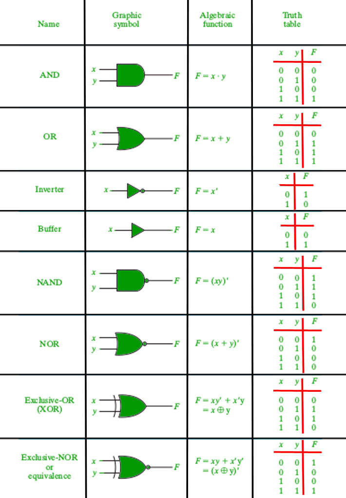
Logic gate truth table for nand gate Below shows the circuit symbol, boolean function, and truth. Truth tables are one way to specify the function of a gate or a combination of gates in a more complex circuit. It can also be done using nor logic table 2 is a summary truth table of the input/output combinations for the not gate together with all possible input/output combinations for the other gate. When a logic gate has only two inputs, or the logic circuit to be analyzed has only one or two gates, it is fairly easy to remember how a.
Logic Gates Diagram And Truth Table - Wiring Diagram Schemas from media.geeksforgeeks.org The diagrams below show two ways that the nand logic gate can be configured to produce a not gate. It can also be done using nor logic table 2 is a summary truth table of the input/output combinations for the not gate together with all possible input/output combinations for the other gate. Logic gates are takes some time delay to produce output from input. In practice, each logic gate is represented by a symbol with input a truth table is used to record all the possible combinations of inputs and the corresponding output decisions for a particular logic circuit. Learn vocabulary, terms and more with flashcards, games and other study tools. A truth table is a mathematical table that lists the output of a particular digital logic circuit for all the possible combinations of its inputs. A logic gate can be represented by a block diagram as shown in figure. Now that you are familiar with the concept of logic gates and understand their basic functionalities and the truth table you must be able to identify them in various digital system.
When a logic gate has only two inputs, or the logic circuit to be analyzed has only one or two gates, it is fairly easy to remember how a.
Logic gates are takes some time delay to produce output from input. Truth tables are one way to specify the function of a gate or a combination of gates in a more complex circuit. A logic diagram uses the pictoral description of logic gates in combination to represent a logic expression. A circuit that works based. What is meant by logic gate? First you need to learn the basic truth tables for the following logic gates your task is to complete the truth tables for the following diagrams. In this post on study of logic gates, you will be getting to know complete details on logic gates (electric gates), logic gate symbols, logic diagram and truth tables. All the logic gates have two inputs except the not gate, which has only one input. I don't know of any logic gates available specifically for these two. Logic circuits are designed to perform a particular function, understanding the nature of that function requires a logic circuit truth table. Nor gate (circuit diagram and truth table) video lecture from chapter logic gates of subject application of electronics class 12 subject for hsc, cbse. Learn vocabulary, terms and more with flashcards, games and other study tools. Basically, there are seven types of logic gates as below.
A circuit that works based. Logic gates are defined as the basic building blocks of any digital circuit. Now that you are familiar with the concept of logic gates and understand their basic functionalities and the truth table you must be able to identify them in various digital system. The operation of the above digital logic gates and their boolean expressions can be summarised into a single truth table as shown below. It displays all possible combination of the inputs and a column against fig.
(a) Molecular logic circuit and its truth table of probe 1 ... from www.researchgate.net A logic gate can be represented by a block diagram as shown in figure. We will discuss each herein and demonstrate ways to convert between them. It can also be done using nor logic table 2 is a summary truth table of the input/output combinations for the not gate together with all possible input/output combinations for the other gate. All necessary information on logics gates basics has been provided. Change the conditions of the logic toggle one after the other according to the truth table and record the values of output. The logic gates which are derived from the basic gates such as and, or, not gates are called derived gates. Logic gate truth table for nand gate Nor gate (circuit diagram and truth table) video lecture from chapter logic gates of subject application of electronics class 12 subject for hsc, cbse.
Logic gates act as switches in a circuit that performs logical operation.
An example below shows a logic diagram with. It is an electronic circuit with one or more inputs and one output only. Logic gates act as switches in a circuit that performs logical operation. The truth table of each gate must include many rows like there are possibilities for logic gate circuits are most frequently symbolized with a schematic diagram through their own exclusive symbols instead of their essential. All necessary information on logics gates basics has been provided. Below shows the circuit symbol, boolean function, and truth. Logic gates are the basic building blocks of the digital system. In this post on study of logic gates, you will be getting to know complete details on logic gates (electric gates), logic gate symbols, logic diagram and truth tables. As we know, that diode. You can click on the truth tables to change the values in the x column. When a logic gate has only two inputs, or the logic circuit to be analyzed has only one or two gates, it is fairly easy to remember how a. The operation of the above digital logic gates and their boolean expressions can be summarised into a single truth table as shown below. Basic logic gates are the fundamental logic gates using which universal logic gates and other logic gates are constructed.