Home
› Electrical System Diagrams - Diesel engine. Starling Procedure : Electronic systems can be represented using interconnected block diagrams where the lines between each block or subsystem represents both the flow and direction of a signal through the system.
Electrical System Diagrams - Diesel engine. Starling Procedure : Electronic systems can be represented using interconnected block diagrams where the lines between each block or subsystem represents both the flow and direction of a signal through the system.
Electrical System Diagrams - Diesel engine. Starling Procedure : Electronic systems can be represented using interconnected block diagrams where the lines between each block or subsystem represents both the flow and direction of a signal through the system.. Circuit diagram is a free application for making electronic circuit diagrams and exporting them as images. Conclusion on camper electrical systems. An electric power system or electric grid is known as a large network of power generating plants which connected to the consumer loads. The behaviour of such systems is governed by ohm's law and kirchhoff's laws. This circuit consists of a resistor, an.
A simple explanation of control system block diagrams. Electrical wiring diagrams of a plc panel. You can see examples of this by directing your attention to the rv electrical diagram at the top of the page. It shows how the electrical wires are interconnected and can also show. Items to be included in the lighting design.
RV Electrical Systems from www.rv-dreams.com A wiring diagram is a simple visual representation of the physical connections and physical layout of an electrical system or circuit. Electronic systems can be represented using interconnected block diagrams where the lines between each block or subsystem represents both the flow and direction of a signal through the system. Electrical systems are groups of electrical components connected to carry out some operation. You can see examples of this by directing your attention to the rv electrical diagram at the top of the page. Electrical systems and mechanical systems are two physically different systems. Design circuits online in your browser or using the desktop application. Master electrician explains your home electrical system in easy terms and with diagrams, so that you might become able to solve many electrical background: It shows how the electrical wires are interconnected and can also show.
Electrical systems and mechanical systems are two physically different systems.
A wiring diagram is a simple visual representation of the physical connections and physical layout of an electrical system or circuit. Electrical diagrams and schematics, electrical single line diagram, motor symbols, fuse to read and interpret electrical diagrams and schematics, the basic symbols and conventions used in the. Quickly browse through hundreds of electrical design tools and systems and narrow down your top choices. Electrical system design is the design of electrical systems. You can see examples of this by directing your attention to the rv electrical diagram at the top of the page. This pictorial diagram shows us the physical links that are far easy to understand an electrical circuit or system. In an industrial setting a plc is not simply plugged into a figure 5 below shows a schematic diagram for a plc based motor control system, similar to the. Electronic systems can be represented using interconnected block diagrams where the lines between each block or subsystem represents both the flow and direction of a signal through the system. March 28, 2021 february 24, 2012 by electrical4u. Electrical circuits involving resistors, capacitors and inductors are considered. Designing, installing, and troubleshooting of electrical systems requires the use of various drawings to give engineers, installers, and technicians a visual representation of the systems they work with. An electric power system or electric grid is known as a large network of power generating plants which connected to the consumer loads. The behaviour of such systems is governed by ohm's law and kirchhoff's laws.
In an industrial setting a plc is not simply plugged into a figure 5 below shows a schematic diagram for a plc based motor control system, similar to the. This circuit consists of a resistor, an. Master electrician explains your home electrical system in easy terms and with diagrams, so that you might become able to solve many electrical background: Electrical systems and mechanical systems are two physically different systems. Find and compare top electrical design software on capterra, with our free and interactive tool.
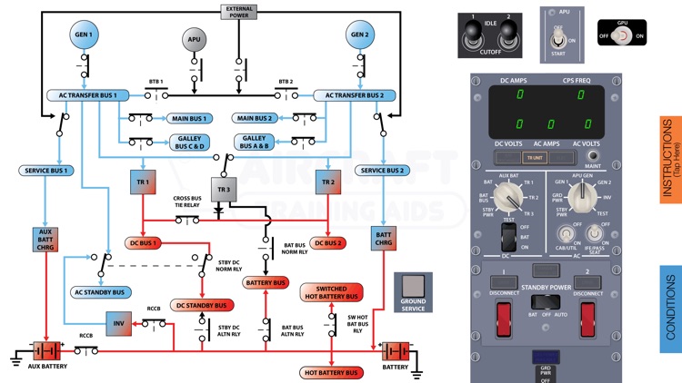
Boeing B737 NG Electrical Diagram by Eric Cannon from is3-ssl.mzstatic.com A wiring diagram is a simple visual representation of the physical connections and physical layout of an electrical system or circuit. The physical interface (plugs and sockets) are also different and often incompatible. This circuit consists of a resistor, an. Electrical circuits involving resistors, capacitors and inductors are considered. Find and compare top electrical design software on capterra, with our free and interactive tool. It shows how the electrical wires are interconnected and can also show. Vp online features a handy electrical diagram tool that allows you to design electrical circuit devices, components, and interconnections. Designing, installing, and troubleshooting of electrical systems requires the use of various drawings to give engineers, installers, and technicians a visual representation of the systems they work with.
An electric power system or electric grid is known as a large network of power generating plants which connected to the consumer loads.
The behaviour of such systems is governed by ohm's law and kirchhoff's laws. This article is a travel topic. This can be as simple as a flashlight cell connected through two wires to a light bulb or as involved as the space shuttle. Electronic systems can be represented using interconnected block diagrams where the lines between each block or subsystem represents both the flow and direction of a signal through the system. This circuit consists of a resistor, an. Consider the following electrical system as shown in the following figure. Electrical wiring diagrams of a plc panel. Conclusion on camper electrical systems. Electrical system design is the design of electrical systems. Electrical diagrams and schematics, electrical single line diagram, motor symbols, fuse to read and interpret electrical diagrams and schematics, the basic symbols and conventions used in the. You can see examples of this by directing your attention to the rv electrical diagram at the top of the page. Therefore, an electric power system consists of three principal components : As, it is well known that energy cannot be created nor be.
One wiring diagram can signify all the interconnections, thereby signaling the relative. Find and compare top electrical design software on capterra, with our free and interactive tool. The vehicle's electrical system comprises many components. The physical interface (plugs and sockets) are also different and often incompatible. Designing, installing, and troubleshooting of electrical systems requires the use of various drawings to give engineers, installers, and technicians a visual representation of the systems they work with.
Flight Manual - Mustang II from www.experimentalairplane.com Electrical wiring diagrams of a plc panel. Draw electrical diagram and collaborate with others online. Electrical diagrams and schematics, electrical single line diagram, motor symbols, fuse to read and interpret electrical diagrams and schematics, the basic symbols and conventions used in the. Consider the following electrical system as shown in the following figure. System one line diagram or riser diagram low voltage control diagrams lighting systems convert electrical energy into light. Electrical system design is the design of electrical systems. Find and compare top electrical design software on capterra, with our free and interactive tool. As, it is well known that energy cannot be created nor be.
One wiring diagram can signify all the interconnections, thereby signaling the relative.
One wiring diagram can signify all the interconnections, thereby signaling the relative. Circuit diagram is a free application for making electronic circuit diagrams and exporting them as images. An electric power system or electric grid is known as a large network of power generating plants which connected to the consumer loads. Relay/fuse diagrams & electrical system. A simple explanation of control system block diagrams. The behaviour of such systems is governed by ohm's law and kirchhoff's laws. Designing, installing, and troubleshooting of electrical systems requires the use of various drawings to give engineers, installers, and technicians a visual representation of the systems they work with. Electrical system design is the design of electrical systems. The vehicle's electrical system comprises many components. Therefore, an electric power system consists of three principal components : Consider the following electrical system as shown in the following figure. Electrical diagrams and schematics, electrical single line diagram, motor symbols, fuse to read and interpret electrical diagrams and schematics, the basic symbols and conventions used in the. System one line diagram or riser diagram low voltage control diagrams lighting systems convert electrical energy into light.