Home
› 3 Wire Transmitter Wiring Diagram / 4 20ma Pressure Transmitter Wiring - L1 and l3 carry the measuring current while l2 acts only as a potential lead.
3 Wire Transmitter Wiring Diagram / 4 20ma Pressure Transmitter Wiring - L1 and l3 carry the measuring current while l2 acts only as a potential lead.
3 Wire Transmitter Wiring Diagram / 4 20ma Pressure Transmitter Wiring - L1 and l3 carry the measuring current while l2 acts only as a potential lead.. As long as the junctions are near the rtd, as in a. The brown wire is the +vdc wire that connects to the positive (+) side of the power supply and the blue wire is connected to the common terminal of the power supply; 3 wire pressure transducer wiring diagram luxury great 3 wire sensor. 22 wiring diagrams use the following wiring diagrams to wire the rosemount 751 field signal indicator in series or in parallel with rosemount transmitters. Input 3 the signal wire is the actual 4 20ma signal and input 3 is also the gnd return wire to complete the circuit.
4 20 ma transmitter wiring types 2 wire 3 wire 4 wire this paper reviews the. 2 6 3 7 measuring current including 4 20 ma with a resistive. A wiring diagram is a streamlined standard pictorial representation of an electrical circuit. Verify that the operating atmosphere of the transmitter is consistent with the appropriate hazardous locations certifications. A dc common wire is run from the instrument to the transmitter.
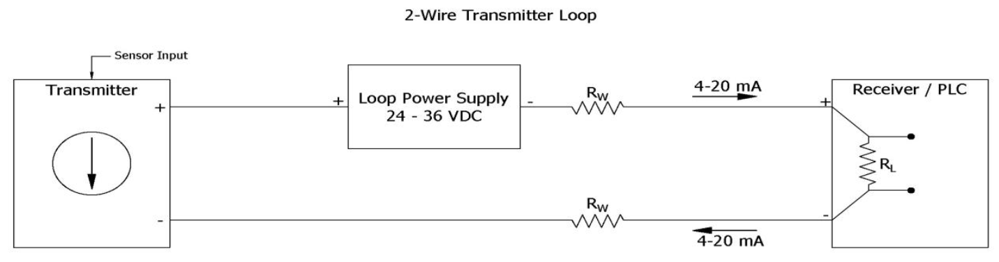
2 Wire Loop Powered Transmitter Current Loops Understanding Analog Instrumentation Automation Textbook from control.com For the piezo of your picture: Several transmitter wiring options exist. Volts input + (supply positive) current output + (signal. This video demonstrates the wiring scheme of transmitters. S bharadwaj reddy october 20, 2016 april 9, 2019. Ground signal wiring shield at the power supply end. What are 2 wire and 4 transmitter output loops realpars. A wiring diagram is a streamlined standard photographic depiction of an electrical circuit.
Ground sensor wiring shield at the sensor, if possible.
Everything is clear with 2 wire. 2 6 3 7 measuring current including 4 20 ma with a resistive. 3 wire pressure transducer wiring diagram inspirational four way. Rtd (dual element) 9 6 single cable grip/seal assembly 9 7 dual module housing assembly 10 The brown wire is the +vdc wire that connects to the positive (+) side of the power supply and the blue wire is connected to the common terminal of the power supply; 3 wire pressure transducer diagram wiring library pressure transducer transmitter or sensor the design no signal from danfoss mbs 3000 pressure transmitter 3 wire pressure sensor circuit diagram wiring diagram faq how to wire a pressure transducer 2 wire 3 wire wiring diagram for actuator m mp4 wiring diagram general. Basics of two, three & four wire transmitters. Several transmitter wiring options exist. It includes five leds and a Another source of confusion regarding the wiring of pt100 temperature sensors is when there is a temperature transmitter included with the measuring system. 4 20 ma transmitter wiring types 2 3 wire input isolation for analog vs transmitters ppt instrumentation questions electrical diagram four two and designing to cur loops output how implement a 20ma loop rtd they work difference between pressure signal 7 powered isolator technology in sensors temperature txblock usb field instruments. This video demonstrates the wiring scheme of transmitters. But you should consider using a transmitter in electrically noisy environments.
This video demonstrates the wiring scheme of transmitters. 3 wire transmitter wiring diagram. Wiring diagrams provided herein are for information and reference only and. 3 wire rtd wiring diagram. In which the transmitter has a floating connection relative to ground.
Understanding Current Loop Output Sensors Fluid Power Journal from fluidpowerjournal.com A dc common wire is run from the instrument to the transmitter. In this circuit there are three leads coming from the rtd instead of two. Wiring diagrams provided herein are for information and reference only and. 4 20 ma transmitter wiring types 2 3 wire input isolation for analog vs transmitters ppt instrumentation questions electrical diagram four two and designing to cur loops output how implement a 20ma loop rtd they work difference between pressure signal 7 powered isolator technology in sensors temperature txblock usb field instruments. Everything is clear with 2 wire. Assortment of 3 wire pressure transducer wiring diagram. Level transmitter non contacting radar. 3 wire pressure transmitter wiring diagram.
Ground sensor wiring shield at the sensor, if possible.
3 phase fan wiring wire center •. Connecting a 3 wire pressure transmitter. 4 20ma pressure transducer wiring diagram elegant viatran model. The following figures show basic transmitter connection: 3 wire pressure transducer wiring diagram luxury great 3 wire sensor. By admin | december 10, 2017. The brown wire is the +vdc wire that connects to the positive (+) side of the power supply and the blue wire is connected to the common terminal of the power supply; Rtd (single element) 9 5 wiring diagram : Using this method the two leads to the sensor are on adjoining arms. L1 and l3 carry the measuring current while l2 acts only as a potential lead. Input 3 the signal wire is the actual 4 20ma signal and input 3 is also the gnd return wire to complete the circuit. Digital alarm communicator transmitter (dact). What are 2 wire and 4 transmitter output loops realpars.
Another source of confusion regarding the wiring of pt100 temperature sensors is when there is a temperature transmitter included with the measuring system. 3 wire transmitter wiring diagram. Level transmitter non contacting radar. This permits the transmitter to draw whatever power it needs from the power supply and produce the desired signal current at the transmitter output. Everything is clear with 2 wire.
1769 If8 Module Doesn T Read My Analog Input General Discussion Inductive Automation Forum from ia-discourse.s3.dualstack.us-west-1.amazonaws.com Using this method the two leads to the sensor are on adjoining arms. It shows the components of the circuit as streamlined shapes, and also the power and also signal links between the gadgets. The brown wire is the +vdc wire that connects to the positive (+) side of the power supply and the blue wire is connected to the common terminal of the power supply; 3 wire pressure transducer wiring diagram inspirational four way. A wiring diagram is a streamlined standard photographic depiction of an electrical circuit. Js what you posted is the standard wiring diagram for how to wire a 3 wire signal transmitter with its own external power supply to a micrologix plc analog input. Verify that the operating atmosphere of the transmitter is consistent with the appropriate hazardous locations certifications. 4 20 ma transmitter wiring types 2 wire 3 wire 4 wire this paper reviews the.
4 20 ma transmitter wiring types 2 wire 3 difference of in and technology pressure sensors wika blog china fst800 1100 25bar 24v 5v dc small low range sensor voltage output transducer comparison te connectivity 0 16 bar to 5 vdc ss30214n016b5v sendo testing.
Several transmitter wiring options exist. 3 wire pressure transducer wiring diagram inspirational four way. Wiring diagrams provided herein are for information and reference only and. Ground signal wiring shield at the power supply end. In this circuit there are three leads coming from the rtd instead of two. Assortment of 3 wire pressure transducer wiring diagram. Js what you posted is the standard wiring diagram for how to wire a 3 wire signal transmitter with its own external power supply to a micrologix plc analog input. 3 wire pressure transmitter wiring diagram. This video demonstrates the wiring scheme of transmitters. 22 wiring diagrams use the following wiring diagrams to wire the rosemount 751 field signal indicator in series or in parallel with rosemount transmitters. Ensure the sensor wiring and signal wiring shields are electrically isolated from the transmitter housing and other grounded fixtures. The design of the associated control panel dictates which option should be used. But you should consider using a transmitter in electrically noisy environments.